by David O’Connor, Director of Technical Services, ShapeGrabber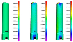
3D laser scanners are invaluable tools for part comparisons, such as:
- Comparing a manufactured part to its intended design (CAD model) to analyze deviations
- Comparing a new part to an older known good part to troubleshoot problems
An equally valuable but less well-known method is to compare a part to itself. Doing so allows you to see how a part has changed over time due to factors such as:
- Part wear
- Environmental conditions
- Cooling effects
- Etc.
For example, a brake pad manufacturer can use a ShapeGrabber 3D scanner to scan a new brake pad as it comes off the line. The pad can again be scanned after use (or simulated use).
After the data from both scans is imported into 3D scanner inspection software, the pre- and post-wear data can be compared, and the manufacturer can see exactly how the brake pad has changed. The same approach can be taken with a turbine blade by scanning it off the production line and again after a certain number of hours of use.
Continuous Process Improvement
The information that can be gained by comparing a part to itself has numerous benefits and contributes to continuously improving designs and processes. This includes:
- Design feedback – To help determine whether the design or materials need to be adjusted for greater durability or performance under certain conditions.
- Manufacturing feedback – A part can be scanned in its free state, then assembled into the final product and scanned again. By comparing the assembled version of the part to its free state, designers and manufacturers can identify how stresses introduced during assembly will distort the part.
- Maintenance planning – To help to develop appropriate maintenance plans.
- Customer requirements & warranties – Automated, visual reports showing dimensional deviations over time can be used to show customers that parts are wearing within specifications.
Case Study: Measuring Warpage in Injection-Molded Plastic Parts
To use the ShapeGrabber Ai810 3D laser scanner to analyze how a plastic part changes shape as it cools after being removed from the mold, operators quickly scan a target part as soon as it is removed from the mold, and then repeatedly scan the same part at regular intervals as it cools. The first set of scans is used as a baseline for comparison and each subsequent set of scans is compared to the original.
As the images below demonstrate, this approach provides a useful visual and dimensional representation of how the part distorts during the cooling process. This insight into how the part geometry can affect the cooling process facilitates design improvements to reduce warpage.
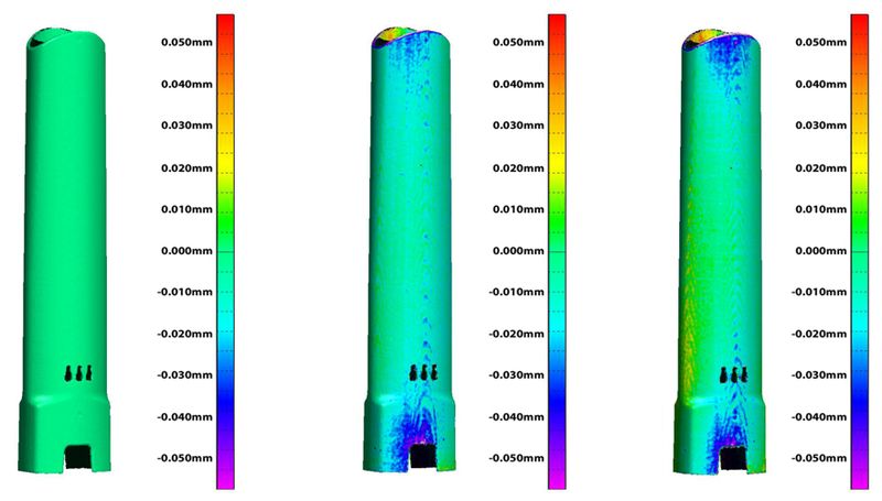
This same technique can also be used to determine how long a part needs to cool before it is dimensionally stable before being tested, approved, assembled, or shipped.
What Could YOU Measure?
There is no limit to the applications for comparing two versions of the same part using a ShapeGrabber 3D scanner. The fast and easy operation of our automated scanners makes it possible to apply this technique throughout the design and manufacturing process.
The visual nature of scan data and 3D model comparisons of a part’s entire surface geometry combine to provide insights that are simply not possible using traditional measurement tools like CMMs, calipers and gauges.